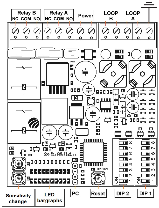
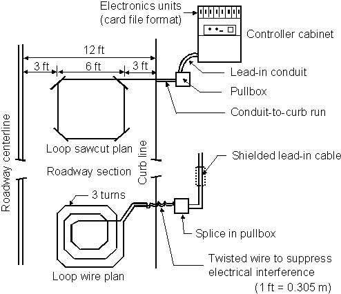
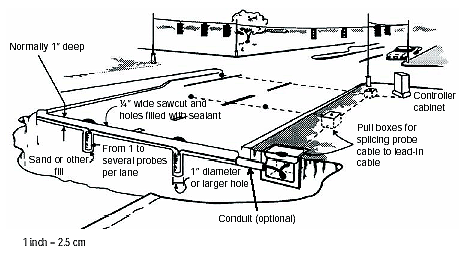
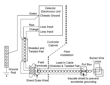
Is a block diagram of a vehicle detector circuit according to the invention for the induction loop vehicle detector description of the induction loop vehicle detector referring to fig.
Vehicle detection loop circuit.
3 an oscillator circuit comprises a road loop 1 and a plurality of capacitors 2 arranged to be switched in circuit with the road loop 1 under the.
Loops are used to stop or reverse a moving gate to allow free exit from or entrance to a site or as an arming loop to allow entrance.
There is a misconception that inductive loop vehicle detection is based on metal mass.
Vehicle detection loops or inductive loop traffic detectors can detect vehicles.
Basics of vehicle detection loops.
Vehicle detection loops called inductive loop traffic detectors can detect vehicles passing or arriving at a certain point for instance approaching a traffic light or in motorway traffic.
Good practice dictates multiple loops and detectors in this situation.
Loop detectors are used in conjunction with vehicle detection loops to detect vehicular traffic traveling or stopping overhead in a roadway these are commonly used to trigger traffic lights and you have undoubtedly traveled over thousands of them without even realizing it.
In other words the relay circuit output will be closed opened the entire time that a vehicle is present over the loop and does not switch again until the vehicle drives away.


